TPW200 BUTT FUSION MACHINE OPERATION MANUAL
Applicable Range And Technical Parameter
| Type | TPWS200 |
| Materials | PE, PP and PVDF |
| Range of diameter × thickness | 200mm× 11.76mm |
| Ambient temp. | -5~45℃ |
| Power supply | 220V±10%, 60 Hz |
| Total current | 12A |
| Total power | 2.0 KW |
| Include:Heating plate | 1.2 KW |
| Planning tool | 0.8 KW |
| Max. Temperature | < 270℃ |
| Difference in surface temperature of heating plate | ± 5℃ |
| Max. fusion pressure | 1040N |
| Total weight (kg) | 35KG |
Introduction Of Machine
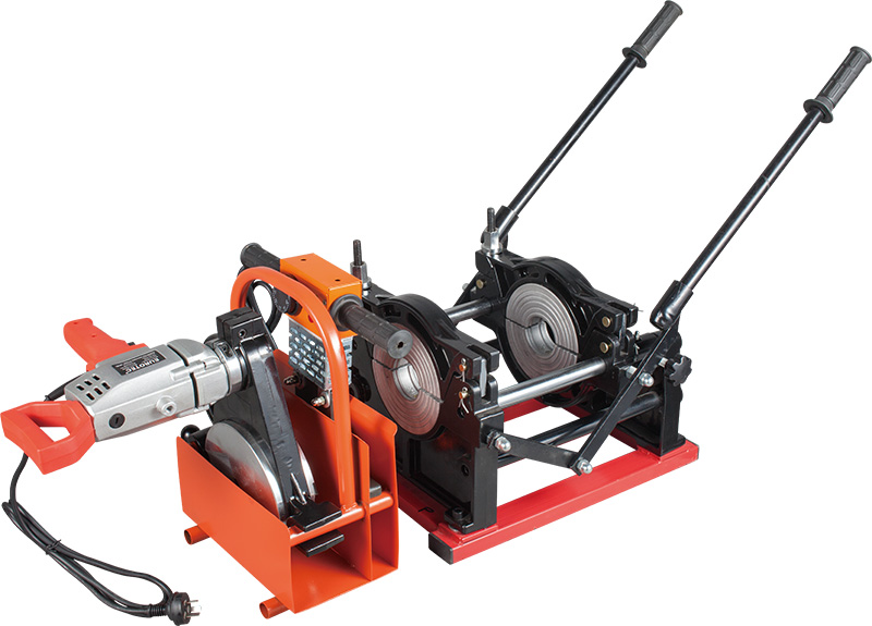
The machine consists of basic frame, heating plate, planning tool and support.

Instruction For Use
5.1 The whole equipment should be placed on a stable and dry plane to operate.
5.2 Before operation make sure the following things:
The power supply is the specified according to the butt fusion machine
Power line is not broken or worn
The blades of planning tool are sharp
All instruments are normal
All necessary parts and tools are available
The machine is in good conditions
5.3 Place appropriate inserts according to outside diameter of pipe /fitting
5.4 Welding procedure
5.4.1. Before welding, firstly, check if there are scratches or fissures on the surface of pipes/fittings. If the depth of scratches or fissures exceeds 10% of the wall thickness, remove the scratches or fissures.
5.4.2 Clean the inside and outside surface of pipe end to be welded.
5.4.3 Place the pipes/fittings and keep the elongated length of pipes/fittings ends to be welded be equal (as short as possible). Another end of pipe should be supported by rollers to reduce friction. Fasten the screws of clamps to fix the pipes/fittings.
5.4.4 Place the planning tool, switch it on and close the pipes/fittings ends by operating two driver rods against the planning tool until continuous and homogenous shavings appear from both sides. Separate the frame, switch off the planning tool and remove it. The shavings thickness should be within 0.2~0.5 mm and it can be adjusted by adjusting the height of the planning tool blades.
6.4.5 Close the pipes/fitting ends and check the alignment. The misalignment should not exceed 10% of the wall thickness, and it could be improved by loosening or tightening the screws of clamps. The gap between two pipe ends should not exceed 10% of wall thickness; otherwise the pipes/fittings should be planed again.
5.4.6 Clear the dust and slit on heating plate (Don’t scratch PTFE layer on the surface of heating plate).
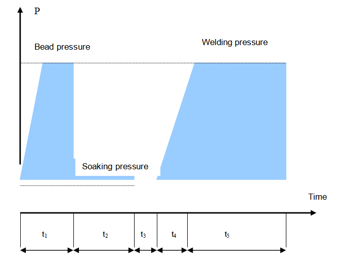
5.4.7 Put the heating plate into frame after it have got the required temperature. Raise the pressure up to specified by acting on the handle till the bead reach required height.
5.4.8 Reduce the pressure to a value which is enough to keep both sides touching with heating plate for specified time.
5.4.9 When the time is over separate the frame and remove the heating plate, join the two sides as quickly as possible.
5.4.10 Increase the pressure until the required bead appears. Fasten the lock device to keep the joint cool down by itself. Finally open clamps and take out the jointed pipe.
5.4.11 Check visually the joint. The joint should be smooth symmetry, and the bottom of groove between the beads should not be lower than the pipe surface. The misalignment of two beads should not exceed 10% of the wall thickness, or the welding is bad.
Reference Welding Standard(DVS2207-1-1995)
6.1 Because of differences in welding standard and PE material, the time and pressure vary in different phases of welding. It suggests that the actual welding parameters should be offered by pipes and fittings’ manufacturer.

|
Wall thickness (mm) |
Bead height(mm) |
Bead build-up pressure(MPa) |
Soaking time t2(sec) |
Soaking pressure (MPa) |
Change-over time t3(sec) |
Pressure build -up time t4(sec) |
Welding pressure(MPa) |
Cooling time t5(min) |
|
0~4.5 |
0.5 |
0.15 |
45 |
≤0.02 |
5 |
5 |
0.15±0.01 |
6 |
|
4.5~7 |
1.0 |
0.15 |
45~70 |
≤0.02 |
5~6 |
5~6 |
0.15±0.01 |
6~10 |
|
7~12 |
1.5 |
0.15 |
70~120 |
≤0.02 |
6~8 |
6~8 |
0.15±0.01 |
10~16 |
|
12~19 |
2.0 |
0.15 |
120~190 |
≤0.02 |
8~10 |
8~11 |
0.15±0.01 |
16~24 |
|
19~26 |
2.5 |
0.15 |
190~260 |
≤0.02 |
10~12 |
11~14 |
0.15±0.01 |
24~32 |
|
26~37 |
3.0 |
0.15 |
260~370 |
≤0.02 |
12~16 |
14~19 |
0.15±0.01 |
32~45 |
|
37~50 |
3.5 |
0.15 |
370~500 |
≤0.02 |
16~20 |
19~25 |
0.15±0.01 |
45~60 |
|
50~70 |
4.0 |
0.15 |
500~700 |
≤0.02 |
20~25 |
25~35 |
0.15±0.01 |
60~80 |
Remark:Bead build-up pressure and welding pressure in the form is the recommended interface pressure, the gauge pressure should be calculated with the following formula.
Expressions:
Welding pressure(Mpa)= (Section of welding pipe × 0.15N/mm2)/(2 × 8 ×8 × 3.14) + Drag pressure
Here, 1Mpa=1N/mm2


